• Skip to primary navigation
  • Skip to content
  • Skip to primary sidebar
  • Skip to footer

CATIA V5-V6 Tutorials

Tips and tricks, tutorials and workflow

  • CATIA tips and tricks
  • CATIA V5 Tutorials
    • Assembly
    • DMU Kinematics Simulator
    • DMU Navigator
    • DMU Space Analysis
    • Drawing
    • General Structural Analysis
    • Generative Shape Design
    • Part Design
  • How to
  • Video tutorials
  • About
  • Contact

You are here: Home / CATIA V5 Tutorials / Generative Shape Design / CATIA Generative Shape Design – beginner tutorial

CATIA Generative Shape Design – beginner tutorial

10/24/2014 by Joe 2 Comments

As an introduction, the module CATIA Generative Shape Design is used very frequently by CATIA engineers, I personally use this module in very work day.

If you want know how to use this module, you should try to use this module to create simple parts at first, like a cylinder, cube or other else simple geometrical form. To open the module CATIA Generative Shape Design you should press: Start -> Shape -> Generative Shape Design. After that type the name of part and I recommend ticking the box Create a geometrical set. This Geometrical set will store all lines, curves, points and other construction elements in one. To be more organized you can create more than one Geometrical set using Insert -> New geometrical set.

In the last part of this article I will show you how to create a simple part using this module.

How to create a Cylinder Using CATIA Generative Shape Design module

  1. First you should create a new Sketch and draw a circle.
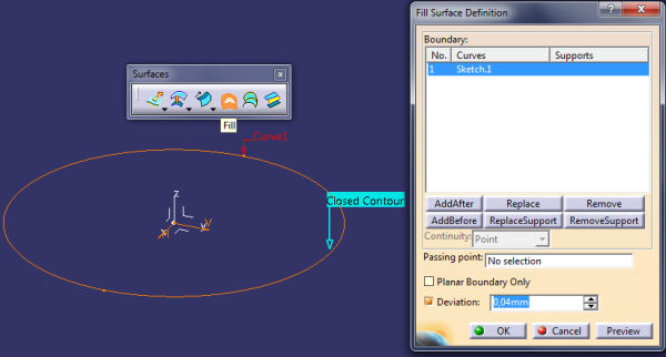
  2. Exit from the Sketch and use command Fill from Surfaces to `Fill` the surface. Select the previous Circle and click OK. Now you have the bottom base of the cylinder. In step 3 I will create the lateral body.CATIA-Generative-shape-design-1
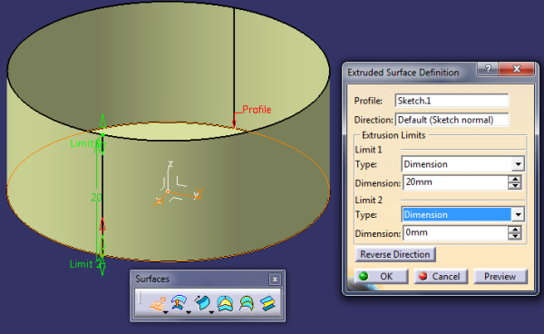
  3. To create the lateral body you should use the command Extrude. To do that, select the base circle created on the Step 1.CATIA-Generative-shape-design-2
  4. Now, I must close the cylinder. To do that select the circle profile resulted from step 3.CATIA-Generative-shape-design-3
  5. Now we have a cylinder, but is designed using simple features (circles, tubes, etc.) similar with 3D design in AutoCAD if you ever use this software until now. To make these three features (first planar circle, 2nd cylinder and last circle) I use the command Join.CATIA-Generative-shape-design-4


To be an experimented user of module Generative Shape Design, you must work many hours creating, modifying and using parts in this module. I recommend you to use a book or YouTube tutorials to learn what can do this module. Is important at first to know all commands and what they can do. If you know all this things and can think like an engineer you will be very impressed by the complexity of the GSD module.

If you are any question, please don’t hesitate to ask me, I promised to be very quickly in answers.

Related Posts:

  • Formula parameterization in CATIA V5 – beginner tutorialFormula parameterization in CATIA V5 – beginner tutorial
  • Assembly Design Tutorial CATIA V5 – beginner tutorialAssembly Design Tutorial CATIA V5 – beginner tutorial
  • Create rapid links to most used CATIA modulesCreate rapid links to most used CATIA modules
  • First steps in CATIA General Structural Analysis – beginner tutorialFirst steps in CATIA General Structural Analysis –…
Your friends will be happy to read this...
Share on Facebook
Facebook
0Share on LinkedIn
Linkedin
Share on Google+
Google+
0Tweet about this on Twitter
Twitter

Filed Under: Generative Shape Design Tagged With: generative shape design, generative shape design tutorial

Reader Interactions

Comments

  1. kiran says

    09/30/2015 at 10:02 am

    Very useful and simple example….is it possible to add thickness to the created surface all at one step?

    Reply
    • admin says

      10/20/2015 at 9:37 am

      In surface mode you can’t set the thickness for a surface.

      You can use translate for a surface to create “thickness” for a surface. If you want to create this “thickness” for more that one surface you can use Join function.

      If you have more questions, please use this form.
      Have a nice day.

      Reply

Leave a Reply Cancel reply

Your email address will not be published. Required fields are marked *

Primary Sidebar


Ask me a question

If you want to obtain punctual answer for your question please tell me what you want to know about CATIA. For this use the contact page.

Recent Posts

  • How to render a part or assembly in CATIA V5
  • Parameterization in assembly module using formula – CATIA V5 tutorial part 1
  • How to use Sectioning in CATIA V5
  • CATIA V5 Drafting Beginner Tutorial – How to create a 2D using Drafting
  • How to close a surface in CATIA V5
  • Part Design Tutorial – Carter (Circular Pattern, Spherical Surface, Complex Design)
  • How to close a surface in CATIA V5 – Part Design and Generative Shape Design
  • Generative Shape Design #1 – CATIA V5 Beginner Tutorial – How to use Extrude and Split
  • CATIA V5 Video Tutorial for Beginners #9 – Part Design
  • CATIA V5 Video Tutorial Beginner #8 – Part Design Support

How to render a part or assembly in CATIA V5

Rendering a part is the last step for a final product. If you want to make a real look for your part, you should use this feature of CATIA application. The rendering time of a part or assembly is different depending to the settings and quality do you choose. For example, if you want to […]

Parameterization in assembly module using formula – CATIA V5 tutorial part 1

Parameterization in assembly module using formula – CATIA V5 tutorial part 1

A short tutorial about how to design an assembly parametric using formula in CATIA V5. At first, you must establish the main parameters that will change the all structure of an assembly (in this case, a screw, a nut or washer). It is simple if you know what you want to do before you start. […]

How to use Sectioning in CATIA V5

How to use Sectioning in CATIA V5

In this article I will show you how to use Sectioning command in CATIA V5, how to export as a new Part to use also in Drawing and more. This command is very useful when you work with large assemblies and you want only a part to make some measurements or to make screenshots for […]

Footer

Recent Posts

  • How to render a part or assembly in CATIA V5
  • Parameterization in assembly module using formula – CATIA V5 tutorial part 1
  • How to use Sectioning in CATIA V5
  • CATIA V5 Drafting Beginner Tutorial – How to create a 2D using Drafting
  • How to close a surface in CATIA V5
  • Part Design Tutorial – Carter (Circular Pattern, Spherical Surface, Complex Design)
  • How to close a surface in CATIA V5 – Part Design and Generative Shape Design
  • Generative Shape Design #1 – CATIA V5 Beginner Tutorial – How to use Extrude and Split
  • CATIA V5 Video Tutorial for Beginners #9 – Part Design
  • CATIA V5 Video Tutorial Beginner #8 – Part Design Support

Contact me

Your Name (required)

Your Email (required)

Subject

Your Message

Enter the below code:

captcha

Categories

  • Assembly
  • CATIA tips and tricks
  • CATIA V5 Tutorials
  • CATIA V6 Tutorials
  • DMU Navigator
  • Drawing
  • General Structural Analysis
  • Generative Shape Design
  • How to
  • Knowledge Advisor
  • Part Design
  • Q&A
  • Video tutorials

Copyright © 2019 · Genesis Sample on Genesis Framework · WordPress · Log in

We use cookies to personalise content and ads, to provide social media features and to analyse our traffic. We also share information about your use of our site with our social media, advertising and analytics partners. Accept Read More
Privacy & Cookies Policy